Yet another score from the "morgue" - this time around, a feature-packed little bundle of audio joy, namely a MOTU Ultralite mk3 Hybrid. This was up for sale as "no longer powering up", and for a two-figure price, i couldn't pass it up.


Same form factor as the Audio Express we took a look at not too long ago, same real nice cast aluminium case, but a lot more ins & outs.
Popping off the top allows us to be greeted by a design so stuffed with things, that it instantly brings back memories of the TC Electronic Studio Konnekt 48. Perhaps not quite as over-engineered, but considering the half-rack form factor, it is nonetheless quite the achievement, i would argue.

Gonna be taking things a little bit "bass ackwards" order-wise this time around, in the interest of... Well, you'll see.

Not totally shocking to see a daughterboards for the top row of jacks on the back, but... In order to shoehorn everything in, even the MIDI connectors and the DC input jack are on their own little daughterboard.
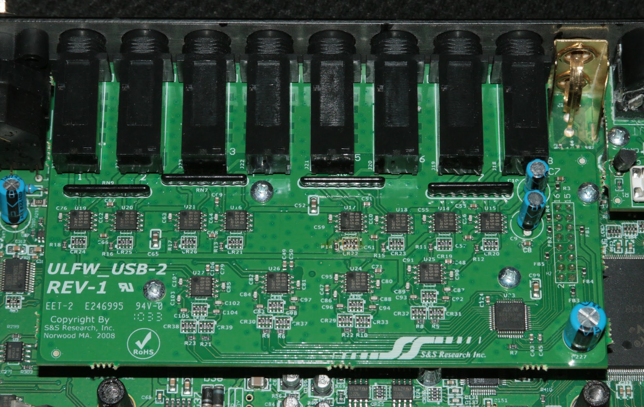
Speaking of the bigger daughterboard, just a quick look-see before removing it for a clearer view of the mainboard. Over in the lower right corner we have an AKM AK4358 8-channel DAC, same as in the Traveler mk3 and the 828 mk3. The rest of the board is filled with passives and a sprinkling of JRC NJM4580's.

And now, behold, the mainboard, in all its cramped-ish glory!.. But moving swiftly on...

Yet more deja-vu on the processing side - an Atmel / Microchip AT91SAM7S256 running the show, an AT45DB161 storing the settings, with a Texas Instruments TMS320C6722 DSP doing the audio processing, assisted by a Micron MT48LC4M16A2 64Mbit / 8Mbyte RAM chip. Pretty much the same recipe as the rest of the "mk3" generation, and why wouldn't you want to "recycle" as much R&D as you can, anyway? Work smarter, not harder...
Near the DSP there's a string of Texas Instruments TPS793 linear voltage regulators, one 2.5V ("PGWI" marking), and two adjustable versions (marked "PGVI") each configured for the minimum 1.225V.

And more "familiar faces" still - a Xilinx Spartan-3E XC3S500E FPGA and a Texas Instruments TLC2933A VCO/PLL. Also in the vicinity, a Texas Instruments TSB41AB1 Firewire PHY and an SMSC / Microchip USB3300 handle the communications with the computer.

The analog-to-digital conversion is done by a Cirrus Logic CS5368 8-channel ADC, with a group of ST TS922I's assisting.

The line inputs go through some JRC NJM4580's, and then into a Cirrus Logic CS3308 8-channel volume control.

An AKM AK4382 and two NJM4580's drive the headphone output.

And another AK4382, an NJM4580 and a pair of TS922's are in charge of the main stereo output pair.

Which gets us to the two mic preamps - nothing what one might call world-shattering here either, namely a pair of Texas Instruments PGA2505's, an NJM4580, and a Texas Instruments OPA2134 buffering the instrument inputs.

Moving on to the power side of things, a Texas Instruments TPS79650 and a National Semiconductor / Texas Instruments LM2990T take care of the +/-5V supply rails to the preamp chips.

Which then gets us to the elephant in the room, as it were. Yeah, that's quite a piece of work right there. Among the (few?) untouched parts in the area, an OnSemi CS51414, handling the bulk of the 3.3V rail (likely for the DSP, the digital comms side of the converters, the glue logic etc), as well as a Texas Instruments TPS61040 boost-converter for the 48V phantom-power voltage. And then there's the unfortunate side of things...
Someone obviously has had a go at this, and the seller i bought it from was surprised to hear about it. I had nothing to complain about, having purchased it as faulty, but it might have been useful and welcome to be aware of such information (had it been available, of course, but as it turns out, it was news all around).
There's one other CS51414 employed with a coupled inductor, that creates (roughly) symmetrical voltages to supply the analog circuitry (+/-10V or so), that had obviously been... well, at least removed, if not even replaced. Trouble is, there are at least two copper pads missing, at least one trace lifted, one torn almost all the way off... And the cherry on top - the chip's the wrong way around, even..!
As luck would have it, i managed to come across a photo of the exact area online, only to confirm the hunch i had after checking the pinout of the chip, from the datasheet.

If you compare this to the photo inside the Ultralite i have here, take note of the chamfered edge of the chip - that denotes the side where pin 1 resides (in this case, in the lower left, as indicated by the marking stripe on the top of the chip). As per the datasheet pinout, as well as the photo of a stock unit above, pin 3 should connect to one end of the inductor (the dark grey octagon near it). On this particular board though, you'll notice the chamfered edge of the chip is pointing away from the inductor. Oh joy...
Oh, and as if that wasn't enough, the linear 3.3V regulator next to it, as opposed to lying flat on the heatsinking groundplane, is lying at quite the angle, on top of a massive blob of solder, and the traces going to its two legs... Well, let's just say they have certainly seen better days. The stock photo indicates it to be an OnSemi LP2950, while this one is a National Semiconductor / Texas Instruments version of the same part number.
Good thing i hadn't dared even power this up before taking a peek under the hood. That's not saying nothing could have already been toasted, but... Anywhosits - while i'm waiting for a batch of new CS51414's, might as well remove the "corpse", and then give the "crime scene" a good going over, and see what can be recovered and what needs to be redone or patched up.

"Yay"... Well, the little electrolytic next to the 3.3V regulator was sitting quite crooked to begin with, so no real surprise half the trace lifted off. Fortunately it only goes to the two quad-pack 4.7k resistors there, so that trace can be replaced with a thin resistor leg. But i think i'll end up scraping some of the solder-resist off the big fat 3.3V trace (that the one end of the positive pad broke off from), and shoehorn in a physically larger capacitor, just to span the extra gap.
Both pads (input and output) of the 3.3V regulator are no more. That's not even the end of the world; there's even a chance i might have a D2PAK-packaged (quite larger than the stock DPAK) 3.3V regulator that i could solder in place, but if not... More resistor legs to the rescue. Probably will have to also rebuild the input trace as well; not sure there's much copper left, where the input pad was torn from.
And then the buck regulator footprint... It just hurts. The trace from pin 1 to the little capacitor (C104, if i'm reading right), is totally torn off the board surface, pin 2's pad is lifted but still attached, pin 5's pad and associated trace going to R212 is no more. All things considered though, i... guess it could have been a whole lot worse?
Stay tuned for part 2...
Where is part 2? The suspense is killing me! LOL. I bought one of these recently that wouldn't power on. It appears to be the same revision as yours. I thought it would be a fun project and possibly an easy fix. When I got inside, I found that U26 (CS51414) had a hole burned through it. Ouch. No other visible damage. Not the easy fix I was hoping for. I would post a pic, but I don't think that's possible here. Any ideas or suggestions?
ReplyDeleteNot quite sure a "part 2" is forthcoming. Reason one being, this particular unit being utterly "fubar'd" - likely all the silicon in this is toast, and i'm not pouring another couple hundred bucks into this. Reason two is that this, as one other mk3 Hybrid i picked up in the mean time, and an 828mk3, have busted LCD's.
DeleteAnd to boot, "of course", in MOTU's infinite wisdom, they're some serial-input custom jobs. The electrical interface wouldn't even be the-end-of-the-world to reverse-engineer, one way or another, but the physical envelope, and the front PCB totally-bespoke-cutout, are not helping either.
Hi Khron and thank you for helping the world understand what is going on in these audio interfaces.
ReplyDeleteI am trying to repair a hybrid ultralite mk3 that exhibits no sound, everything is working , unit boots up fine, it connects to the computer and it can be remotely controlled but there is no sound from the inputs or the outputs.
I am suspecting either the spartan fpga or the Texas Instruments TMS320C6722 with its memory.
I have checked all the Vcc going to these chips, and all look good nothing is missing.
If it was the spartan fpga problematic , I think there should be an error while booting the unit, so I thnk that that the problem is TMS320C6722 or its memory.
Do you have any ideas about how to troubleshoot from there?
thank you !
At this point, i would check the analog supply rails (feeding the opamps and the converters). If those check out fine, i'd move on to the clock signals going to each of the converters, as well as the serial audio data lines - these would require the use of an oscilloscope capable of at least 20MHz bandwidth (the master clock will be in the region of 24.5MHz).
Delete