This summer's "already" been quite fruitful, gear-scoring-wise anyway. This find cost me a colossal 86eu, with allegedly none of the outputs working. This, in the context of it retailing for a somewhat eye-watering 500eu(!!!) or thereabouts, brand new. On the bright(?) side, it came with the original packaging, manuals still in their plastic bags, as well as a USB and a Firewire cable to boot, both also still factory-packed. So why not?


Right off the bat, that's one interesting detail on the back - the DC input jack is "agnostic", which is something you don't really see everyday. Other than that, not a whole lot to write about, regarding the outsides. Half-rack version of the venerable MOTU cast aluminium (yes, it's "aluminium", not "a-loo-minum") enclosure, the kind of thing you could use for self-defense, if need be. But i'm just speculating... Regardless, time to pop the lid off.

Cute board manufacturing details - the top daughterboard was included in the main board, and then separated post-component-populating. Nothing wrong with minimizing waste, with the added benefit of not wasting production costs either.
Speaking of the daughterboard, among other things, it carries the DC input socket. That then goes through a 0.51 ohm resistor and a 1A bridge rectifier. Probably the simplest way to achieve the polarity-irrelevant capability of the powering.
But since we started with the power supply, might as well dive in. A tiny little Texas Instruments TPS61040 supplies the phantom power voltage, with an added voltage multiplier, in order to safely but practically exceed the maximum output voltage of the regulator itself. Two OnSemi CS51414 handle, on one hand, the +6V rail, and on the other hand the -6V rail. The values are an educated guess; the maximum supply for some of the opamps used here is +/-7V, and the positive "bucked down" rail powers the phantom power regulator, which can only take +6V.

A Texas Instruments TLV1117 adjustable regulator provides the 1.5V(?) rail likely to the FPGA (see disclaimer above).

Also likely powering the FPGA core is a Texas Instruments TPS73001 adjustable linear regulator, probably connected to provide 1.2V or so (the minimum it can).

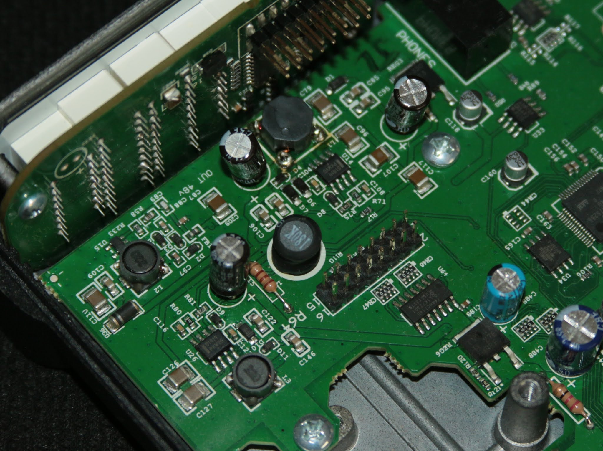
A better look at the CS51414 handling the negative analog power rail, as well as an OnSemi LP2950-33G 3.3V low-power linear regulator feeding much of the digital circuitry.

The supplies for the analog side are cleaned up by a JRC NJM2846 for the +5V rail, and a National Semiconductor / Texas Instruments LM2990T for the -5V rail.

Moving on to more interesting(?) things, we have the main workforce of this thing - an Atmel / Microchip AT91SAM7S256 microcontroller running the show, and a Xilinx XC3S400A Spartan-3A FPGA. In between these two is a Texas Instruments TLC2933A PLL clock generator, while the firmware is stored in an Atmel / Microchip AT45DB181D 16Mbit / 2Mbyte flash memory.


Computer communication is interfaced via an SMSC / Microchip USB3300 and a Texas Instruments TSB41AB1, for the USB and Firewire, respectively.

Moving on to the analog side of things, we're greeted by a relatively familiar sight. As opposed to the times we've seen the "classic" PGA2500, this time the updated version is used, the Texas Instruments / Burr-Brown PGA2505 digitally-controlled preamplifier. I'll leave determining the differences between the two, to you; i'm not all that curious, or fussed about it. Other than that, a pair of Taiwan Semiconductor DBL103G bridge rectifiers as input clamp proctection for the microphone inputs, a pair of Rohm BA4580's, likely handling the instrument inputs.

The analog-to-digital conversion is performed by a Cirrus Logic CS5364, with the aid of a few ST Microelectronics TS922 opamps. Interestingly enough, there's also a Cirrus Logic CS3308 8-channel volume control chip - that must be how the line input trim is done, as well as the line outputs and possibly (if not likely) also the headphone volume. The digital-to-analog conversion is delegated to an AKM AK4358.


Nothing terribly interesting on the back of the UI-board, only a few NXP / Nexperia 74HC165 shift registers for reading in the encoder inputs, and a few 74HC595's driving the LEDs.
Now, as mentioned in the intro, i had bought this with the reported fault that the outputs were not working but, surprisingly enough, all went well during my testing, no hiccups or anything. I even ended up playing some audio from Youtube out one pair of line inputs, looping that through my Scarlett 18i20, coming out the S/PDIF back into the Audio Express, and back to the Scarlett again via S/PDIF, with no issues whatsoever, so... Despite not having done anything really, i'm calling it good!
No comments:
Post a Comment