
The last issue i had to take care of, back then, was the (apparent?) shorting to ground that some of the I2S clock signal lines, coming out of the Dice II chip. Fortunately, it has several sets of these clock output signals in use, so between cutting a couple traces and adding some wire jumpers, i managed to put together and distribute a healthy set of clock signals to all the ADC & DAC chips that required them.
PS: It seems that the original link for the schematics of this unit is dead nowadays ("thank you", Music Group?), but for the sake of completeness and posterity, i've reuploaded it right over here.

Trouble is, a few months ago, analog inputs 11-12 quit working. The associated ADC was receiving the three necessary clocks alright (MCLK, BCLK and LRCK), but it was outputting precisely squat on the audio data pin. "Sure enough", that particular line measured about 100 ohms to ground, pretty much same as the dead clock lines did.
As it happens, i had collected a faulty "little brother" of this unit, namely a Konnekt 8. Largely the same design, just reduced number of ins & outs, but otherwise using the same major silicon. Well, that's the decision made, then - the Dice II from the Konnekt 8 is gonna get swapped into the big'un (ie. the Konnekt 48). On a semi-related note, i'll have to check whether the "dead" clock lines are used or not, on the Konnekt 8 board, but that's a project for another time...
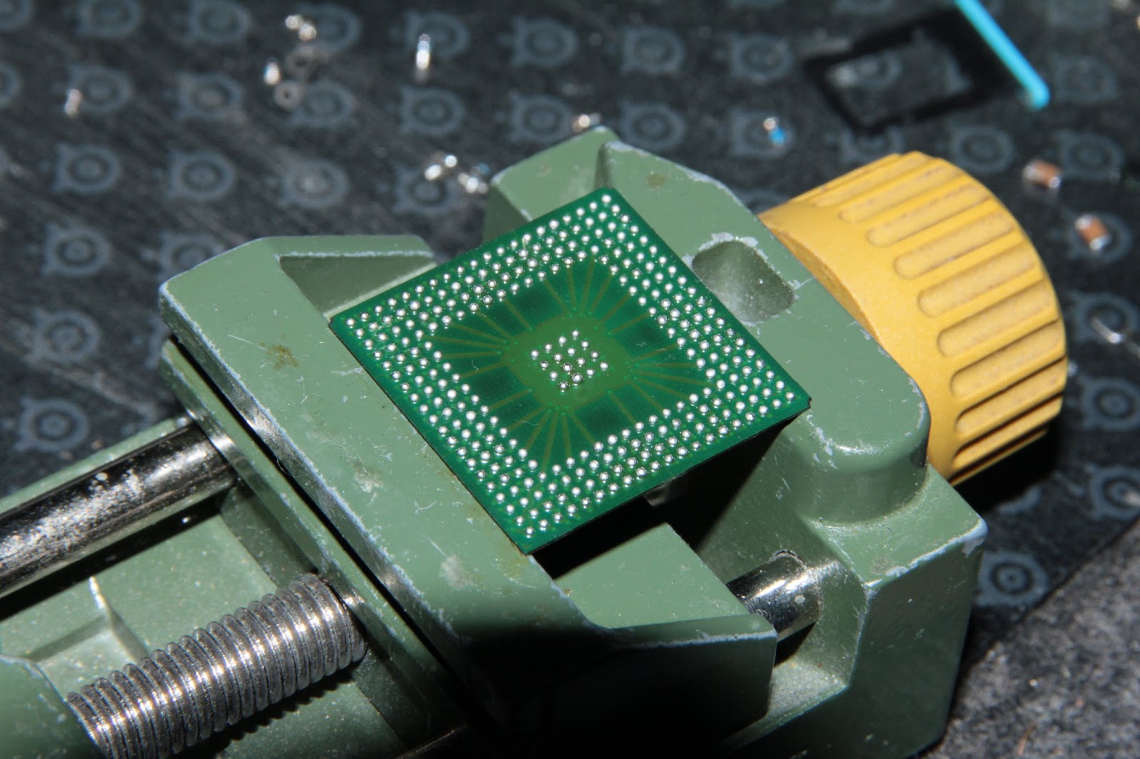
After a thorough fluxing of the chip edges, removal of the two neighbouring quartz crystals, and masking off the surroundings with aluminium tape, the removal succeeded smoothly enough. No lifted pads, no torn traces, or any other drama / issues of any sort. Reballing the chip "had to" happen manually, by virtue of not having any sort of stencil, or solder balls.
Fortunately, i recalled having been shown a video a few years ago, with a guy manually reballing a chip out of some old Nokia phone.There's a good chance it might've been this one. Given that the chip in question in my case is a reasonably-sized (27x27mm) one, with decent-sized pads, i managed to get away without requiring a microscope.


The first round of melting the "spikes" into balls prompted a bit of corrective work - a few of the balls turned out unreasonably small, while a couple others turned out a bit too "fat". Neither is desirable, if you want all the balls to melt and stick. The too-small ones may very well not reach to bridge the gap between the chip and the board, while the too-big ones run the risk of getting squashed enough to touch and coalesce with the neighbouring balls / pads, leading to signals (or worse, supply lines) getting shorted together.
Second round of melting yielded slightly more workable results (in my humble opinion, anyway). We're gettin' there, folks, we're gettin' there...
The bad Dice II's off the Konnekt 48 board as well - clean enough lift this time too. After i cleaned off the pads on the bottom of the (apparently) bad chip, i figured i'd make double-sure i was doing the right thing. Fired up the multimeter, and compared readings between the two chips, and sure enough, the bad one does indeed have shorts to ground where the good one (the one from the Konnekt 8) does not. So far, so good...
Soldering on the good chip went as well as could be hoped. After soldering back the two quartz crystals as well (previously removed as to not "cook" and thereby destroy them), plus the wiring from the power supply, i powered the thing on and... Whaddya know - getting the boot animation on the LED level meter display. The thing works!!!
Scoping out the traces where i had previously cut them showed all the clock signals just as one would expect. Now to reconstruct said cut traces...

Done aaaand done. All working as well as could be expected. With just one exception, but which isn't a fresh issue - the ADC on inputs 3-4. I knew something wasn't quite right i believe since the first round of repairs, but now i got total confirmation.

I had read that this Konnekt line of interfaces had had issues with the mic/instrument input gain potentiometers, so i figured that must be why inputs 3-4 weren't quite working on my 48, but that's not it. The signal's perfectly fine all the way to the ADC inputs, but the serial data coming out isn't right. If memory serves, it wasn't right even with the original chip. Guess i'll have to see where i can source a spare AK5386 sometime. Fortunately it's a small TSSOP-16 package, so swapping it out should be undramatic enough.
But yeah, one more successful endeavour! Me happy...
Thanks, much appreciated. Well, if you want the minimal cost / work solution, you can replace the TSB in only one of them (the "middle" one in the daisy-chain). Although for maximum safety, yeah, you'd want to replace both.
ReplyDeleteBut if only one port works on each, as you might've read on Badcaps, conceivably the TVS diodes could also be shorted (they were, in my case). After you remove each TSB, make sure you measure for shorts between the four data lines on each port, and ground - i'd go with the diode-test mode on the multimeter (red probe on ground, black probe on each data line).
Helped tons. Just wanted to thank here as well. Awesome interfaces! Awesome post as well.
ReplyDeleteGlad to hear that, and thanks for the kind words.
Deletecould you shed some more light on what you heard about the input gain potentiometers not working? I am getting very little input from mic 1-4 now and if I jingle the input knob sometimes I get an increase temporarily. Anthony toneman33@yahoo.com
ReplyDeletePosting your full email address anywhere publicly online is begging for spam, just FYI.
DeleteNo idea if the TC support forums are still online anywhere, but i seem to remember there even being a recall at some point, of various Konnekt interfaces, due to the potentiometers crapping out.
There it is, even found the service note regarding the potentiometers.
I am in a similar situation and I have found your wonderful blog. I have a TC Electronic Studio Konnekt 48, won't boot with or without firewire connection. Only the blue light around the power buttom appear but no "TC logo" at boot and no connection with computer. I have been looking at this entry and I have seen that you mention that you changed a capacitor, my hope is that it might be one of the power supply sections, is that possible? Thanks for your great work.
ReplyDeleteYes, the capacitor(s) on the 3.3V supply are very prone to getting cooked. My SK48 takes a good minute to manage to successfully boot up, from cold, even after replacing those capacitors a second time. That's one reason i keep it on all the time...
DeleteThank you for sharing this. I've replaced 2 bad caps recently (K48 couldn't turn on), where the power supply connects to the main board. Now everything is working fine again, except random BSOD's while using it with particular audio software or turning it off, while it's in use, but I guess it can be drivers issue, as it has never meant to be used in Windows 11. Still is it worth to replace all electrolyte caps in the unit? Can it make it more stable and prevent BSOD's?
ReplyDeleteI kinda doubt there are hardware issues to fix, that would affect software stability. I'm using mine on Windows 10, and it sometimes freaks out and switches sample rates at random and so forth. But i don't blame it, it's "not supposed to work", almost.
DeleteBy the way I've resolved BSOD's by raising voltage on my RAM ( Crucial Ballistix) to 1.5V from default 1.35V. Not sure how it's connected, but now everything is very stable and can do everything I want to K48. Windows can even usually survive the K48 power off while it's busy with some audio app now, which was impossible in the past and caused BSOD 100% of the time.
DeleteWell then, the BSODs weren't necessarily caused by the K48 itself..(?)
DeleteHey Khron,
ReplyDeleteSomebody on the forums linked this post as a guide on how to fix my problem, can you tell me which thing would I need to approximately replace? Thank you!
Not to be a burden, I have a problem with my desktop konnekt 6 where its turned on and has power through firewire, but there is no light shining on the konnekt to signalize that it's connected. Also, the mic input for example is all messed up and the sound is clipping even on low signals, and it sounds all distorted.
Guessing something is definetely fried in there, maybe you have a clue? I'm gonna open it and I will reply so someone has a clue what I did.
"Power through firewire" doesn't mean much - the power pins are separate from the four data pins. The interface chip is a frequent victim (TSB41AB1)...
DeleteSchematics and board layouts can be (still) found here:
https://service-tcgroup.tcelectronic.com/konnekt-6_.asp
Regarding the mic input, not sure you can trace down any particular issue without access to (and know-how about) an oscilloscope. Unless you really wanna shotgun ALL the parts from the mic input connector up to and including the ADC...
Hi, Khron. So far been using my K48 and Konnekt Live no problems. However, the P1 preset memory became corrupt. TC Near control panel will crash if opened with that preset recalled from the remote. Weird characters resembling a "y" with two dots on top appeared in the label of every channel. I could see those for a second or two before the panel crashed.
ReplyDeleteFortunately, the remote lets me switch for another DSP preset so I can get into control panel and reset the unit. So no permanent issue, fortunately.
Wanted to ask, what do you think could be a cause for preset corruption? Maybe some low voltage or similar?
Thanks.
Some sort of "brown-out" during the saving of that preset is a possibility, sure. Or just the flash chip has a wonky area. Have you tried to save another setting to the P1 preset (thereby overwriting it)?
Delete