And here we are, on the third and final(?) part of the modding journey involving this little fella. As presented in the previous post, i managed to "persuade" the thing to power up fully despite not being attached to a computer, only to a USB-connected 5V source. But now, the time has come to integrate what is virtually a "power-bank", within the enclosure, and thus have the Saffire be entirely "self-sufficient", as it were.

A while ago, just for kicks, among some other chips i needed, i grabbed a few Injoinic IP5306 powerbank controllers from AliExpress. Can't 100% recall just how i came across this particular model (might've been in a powerbank i fixed for an acquaintance, a while ago), but regardless, it's a handy little package. It's pretty clever, too - even with a current-limited 5V input, it only draws as much current as the supply will allow until sagging to about 4.75V (the lower limit of the standard 5% tolerance), so it should pose no issue even if charging from a computer USB port (usually only rated for 500mA).
But incorporating this into the Saffire's power circuitry, most importantly without losing or sacrificing any of the original functionality, required a bit of care, planning and "surgery". One step at a time, though.
Since i didn't need any particularly fancy features, and since i wanted to put it together quickly, i once again went with "ye olde" scoring-a-blank-PCB-laminate method. Since the chip is already highly integrated, and the schematic is the one from the datasheet, all the external components needed were the inductor, a few capacitors and a couple resistors. And i also tried to ensure plenty of nice fat ground-plane to aid with heatsinking the chip, even though it shouldn't need to handle any significant load. It's rated for over 2A of discharge current, but the Saffire shouldn't need more than 400mA or so.

The circuit was small enough to fit onto an off-cut of laminate. In order to ease the assembly and, if necessary, service later on, i decided against hard-wiring this power-board to the main board of the Saffire. Instead, i went with a 3-pin 0.1" header, along with a 3-pin fan header scavenged from some old computer fan in my parts bin. Same for the on/off button in fact, albeit with another sort of 2-pin connector. Also, i was pleasantly surprised to see that, with enough flux, persistence, and a wide flat tip, the metal of the top case, despite being some sort of steel, still managed to allow solder to get a moderate grip. Even though i had applied a generously wide piece of 3M 9087 double-sided tape between the circuit board and the top casing, i still tacked on a couple of pieces of solder-wick, to help fasten the board. Adhesives rarely hold up to heat very well, and even though that shouldn't be an issue, why not take a couple minutes to try to prevent such issues, right?

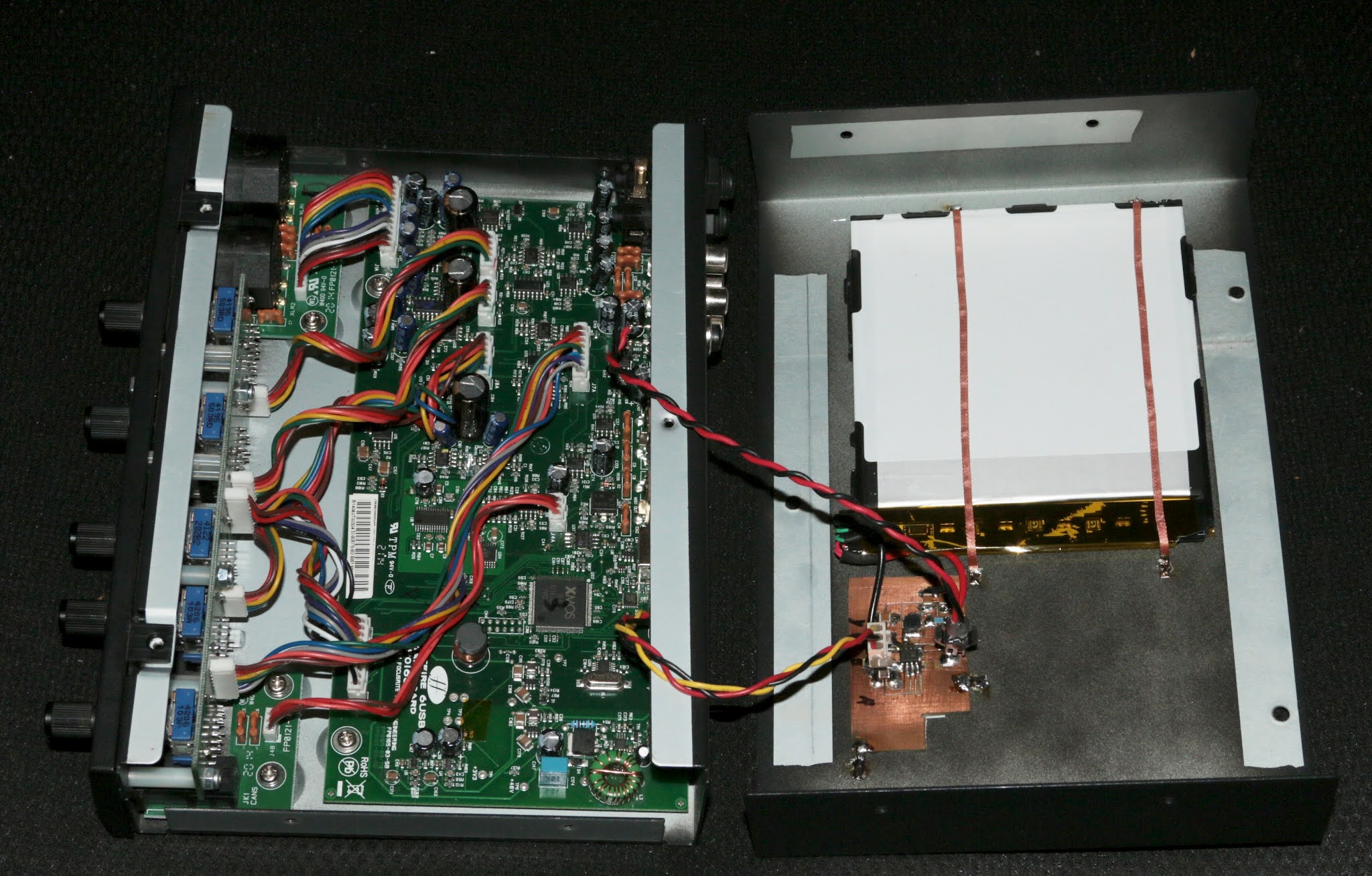
As for the battery, i had collected a few used ones from Samsung tablets along the years (among a few others), and i settled on a two-parallel-cell 6.8Ah(!) one. Fortunately, the plastic "frame" it's taped into, lent itself to being cut to allow the two cells to be folded over each other. Inside the case of the Saffire, i had plenty of space to allow for more thickness, and the length and width of the single cells fit just right. Cue even more 3M 9087 tape, both between the two halves of the battery, as well as the battery and the top case. That, plus a pair of solder-wick "straps" to help hold the thing on.
And now, on to the electrical side. As luck would have it, Focusrite had decided to use a common-mode choke on the USB power input (same as could be seen in the 2i2 and 2i4 teardowns here, in fact). That consists of two inductors wound around the same core - in this case, one in series with the 5V input, and one in series with the ground. As such, this offered an easily-accessible spot to splice this circuit in, without needing any trace cutting or other type of unsightly "mutilation". That's not to say it ended up particularly aesthetically-pleasing, but hey - it IS functional.

The drum-inductor in the vicinity was temporarily removed to allow better access to the "surgery" area. The method i decided to go with was to solder the input-to-the-powerbank wire to the 5V-output terminal of the choke, the 5V-from-the-powerbank onto the corresponding pad on the board, and resolder the common-mode choke's input terminals back to their rightful place. And blob some solder onto the ground-side output terminal of the choke...


Quick recap: red goes from USB 5V input to the powerbank; yellow comes from powerbank to power the mainboard; black is ground. As may or may not be visible, there's a couple layers of kapton tape between the red wire soldered to the choke, and the yellow wire soldered to the board (where the respective end of the choke used to be).
And now, for some of the gritty(?) details. The IP5306, while possessing a low-load timeout / power-saving feature (turning itself off after ~32sec of "no load"), the detection threshold is 45mA, while the Saffire itself draws 350-400mA at idle. That means there's no real way of using the auto-standby feature, so a manual on/off button is required. Nothing too complicated, just a momentary normally-open single-pole switch, pulling the "key" pin to ground.
For aesthetic, as well as practical reasons, i had my mind set on a panel-mount push-button switch. Unfortunately though, as luck would have it, i had none, but an old friend did actually have one at hand. It turned out to be even more low-profile than i had expected, which was very welcome.
Now, since it would stick out from the mounting surface, i figured i should try to mount it so as to at least partially protect it from accidental actuation, and that spot turned out to be in the vicinity of the RCA output connectors on the back. Ripping into the already-crowded front panel was never an option anyway.


And here's the end-result - not too shabby, if i may say so myself. And it works just fine, to boot! The plentiful battery should offer more than a few hours (8-12, perhaps?) of wired-power-free operation easily. And now that i think about it, in addition to the initially-intended role as a headphone amplifier, this could even be used as a two-channel DI-box.
No comments:
Post a Comment