Buuuuut that brings us to what might as well amount up to the proverbial "elephant in the room" - the power supply. No markings or label anywhere on it - if i didn't know any better, i could almost say it never had any (no adhesive residues or anything). Fortunately, it was held together with four Phillips-head self-tapping screws, so "disrobing" it wasn't unecessarily traumatic. That being said, what greeted my eyes, sort of WAS.

This, as far as i'm concerned, is close enough to the definition of a "charlie-foxtrot". I'm not sure what died in there, or how, or why, but it couldn't have been pretty. Lots of soot-like residue on the board, signs of "thermal distress" in some places, and even some sort of dried-up leakage(?) left-overs. But that's almost "okay", because the bottom of the board turned out to be even more shiver-inducing.

Yep, that is some utterly APPALLING primary-to-secondary clearance. In the "tightest" spot, it can't be much over 1mm - ok, maaaaybe 1.5mm (~1/16"), but that's being really generous... Nope, laser-eyeball was right, that's one whole milimeter right there (40 thou, roughly 3/64 in imperial), and no more than that. And as if just to add insult to injury, some of the trace routing is simply baffling. They milled an isolation slot under the optocoupler (lower edge of the photo), but just next to it, the traces get right up next to each other - why even bother?
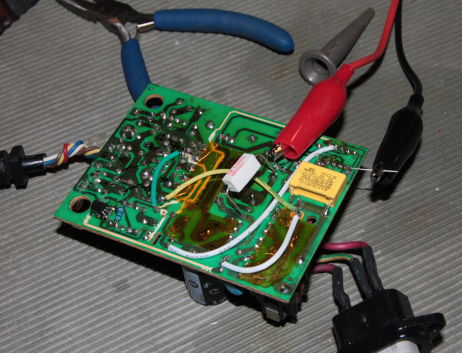
Consequently, the first step, even before plugging the thing in to test, was to remove (ie. scrape / shave off) the offending traces from the board, and rerouting them via wires, on far less hazardous paths. The longest (and most puzzling, design-wise) was the feedback signal from the optocoupler to the PWM controller - can't help wondering what would motivate one to place the two almost on the furthest-from-each-other corners of the board. Like... WHY?!?!?
<deep breath...>
And now, on to the thick of it, the power supply revival (hopefully). Right off the bat, full re-cap, no questions asked. Well, when i say "full", that needed to skip over the bulk filter cap (68uF 400V, Sancon GR) for the rectified mains, for two big reasons: closest thing i had was a 22uF, and it still measured within the 20% tolerance spec. But the two small ones on the primary (Vcc and Vref filtering for the PWM chip) and all the ones on the secondary were doomed to get discarded (ie. to the electronics dump).
Two "Rukycon", ie. fake Rubycon, three unknown brand (with some triangle-logo thing) and one H.E.C., got replaced with a pair of Chemi-Con KZH 1200u/25V for the first filter stage for the +/-15V rails, and the other four on the secondary (12V, 48V and second-stage +/-15V filters) got swapped with Panasonic FR 100u/63v. The two on the primary were replaced with a Rubycon YXJ 47u/63V for the Vcc filtering, and a Nichicon VZ 100u/10Vfor the Vref.
Next up, the little blue ceramic caps. Normally, in proper and/or brand-name power supplies, you'd see mains-rated Y2-class capacitors in those positions (live to earth and neutral to earth, and a third one between secondary ground, and primary ground). Here, we had some random 2KV rated ones - out they go. Also, what is (or should be) an X2-class capacitor (between live and neutral) is some random 100nF/630V capacitor - that's getting swapped out as well, obviously.

While we're on the primary, the soot-cover seemed to be centered around what was now that yellow-orange disc-shaped component. Couldn't tell you what it is (measures around 0.15 ohms), but judging by where it is in the circuit (between one half of the common-mode choke, and one "corner" of the discrete-diode bridge rectifier), you'd most often see an NTC - negative temperature coefficient thermistor - in that position, with the main role of inrush-current limiting. Going by how physically thin it is, my guess is the pre-existing component there is actually a PTC (see link above), given the low resistance reading, but which really shouldn't be there.
Now, by the look of the underside (solder side) of the board, the soot-marks, the clean-looking out-of-place PTC, and perhaps even the TI-branded TL3842, someone must've had a go at this. You'll note that pretty much all the solder joints look like they've been (manually) retouched, going by the flux residue "halo" around each pad. Since the capacitors are nowhere-near-half-decent brands, it would be ridiculous to imagine the OEM of this actually sprang the extra bucks for a genuine brand-name PWM. Also, considering the two nearest resistors to the chip look well-charred (but measure ok), in addition to the stock ex-thermistor, my guess is the factory-installed PWM "released the magic smoke" too.
No idea what the main switching element is, since it's obscured by the transformer. Couldn't really be bothered to extract it, since it wasn't shorted / blown, but i'd expect it to be something like a 4A 600V MOSFET or so, since this whole thing barely has to supply a dozen or two of watts anyway. Other than that, things looked reasonably ok.
Bad news though - the thing wouldn't turn on. That prompted me to start testing the silicon (ie. diodes on the secondary, plus the one on the auxiliary winding on the primary, that supplies the PWM chip) - turned out all was well. The obvious hack-job of resistors around the TL431 that was part of the feedback circuit redirected my suspicions toward that; swapping it out didn't help either. Resistors around the PWM charred made me swap that out as well - the closest i had at hand were a pair of UC2843's (same thing as TL3842, just starting at a lower voltage). You guessed it, same as before, no dice. It's at this time that i made an appeal to the assistance of an old buddy of mine, who proved to be a highly valuable source of input, as well as a competent partner to bounce ideas off of.
Voltage readings with the "stock" chip showed Vref around 1V while the Vcc wiggled around the 12V mark - seemed like the chip was on the brink of starting up, but with the Vref (which would normally be 5V) being so low, the internal oscillator wouldn't start, and as such, no switching of the MOSFET and thus no power. With the replacement one, more or less the same story, just slightly different voltages: 8V for the VCC (normal-ish for the part), and 1.4V or so for the Vref. Still nowhere near being ok.
Stuck in an ammeter in series with the start-up resistor (100K from the positive of the rectified mains) - a mere 2.8-3mA draw, on average, so nothing out of the ordinary there. I then removed one end of each of the two ("toasty") resistors connected to the Vref pin (one going to the compensation pin of the PWM, and one going to ground). No change, once again.
<grumble-grumble> Very well, bringing out the big guns - (isolated) bench power supply for the PWM chip. With one leg of the start-up resistor removed, cut the trace coming from the auxiliary winding's rectifier diode (as a secondary benefit, to be able to probe that voltage with no load). This way, the mains didn't even need to be connected, which reduced the hazards of probing around.
And whaddya know - the damn thing powers up just fine. Well, the PWM chip itself, anyway. The meter on the power supply reported a 14mA draw, perfectly in line with the specs. With the UC2843, it started up fine even when supplied with just 9V. Reference nice and steady at 5V, oscilloscope probing confirmed the operation of the oscillator as well. Groovy!..
Hooked up the mains as well, and the indicator LED on the secondary lit up just fine. Secondary voltages looked pretty ok, at +/-16.3V, 12.3V and 45V. Well, the latter seemed a bit low, but nothing critical. But back to the probing and troubleshooting...
Since the auxiliary winding was disconnected from the PWM, it had no load on it whatsoever, and probing it indicated it was putting out about 15.7V, well enough above the undervoltage-lockout threshold. Despite having tested the associated rectifier, i replaced it with a 1A ultrafast diode, just to make sure the original one wasn't (electrically) leaky or whatever. To make double-sure, the 10ohm resistor it had in series, which was a bit "tanned", got replaced with a parallel pair of 22ohm resistor (mainly because i didn't have 10's at hand, i admit). To aid in testing, and having noted the PWM's draw being anywhere between 13-16mA, a 1K 1W resistor was a close-enough-to-equivalent load.
These latest measures resulted in an unloaded aux voltage of about 18.7V. Connecting the 1K load resistor dropped the voltage down to around 12.2V - still more than enough to run even the previous chip (the TL3842). Finally, some (useful) progress!.. Alas, upon reconnecting the 100K startup resistor, as well as the aux supply to the PWM chip, brought nothing but further disappointment and confoundment - Vcc at 8V, and Vref once again (or rather, still?) around the 1.4V mark... This is getting utterly annoying.
Come the next day, and i was giving a brief run-down of this ordeal to a former neighbout and office-mate, when after a few back-and-forths, he had a brainwave - what if, for whatever reason, the "start-up cap" (ie. the PWM's Vcc filter cap) didn't have / hold enough charge to keep the chip / oscillator running past the first switching cycle, and by falling flat on its face, was stuck in a permanent start-up / undervoltage "vicious circle"? A few minutes later, the adding of a second 47uF cap in parallel with the one already on the board, answered that question. The damn thing (finally) started up on its own!!!

To make the thing a bit less janky (and to help it fit in its casing), a 100uF/25V Rubycon YXF replaced the parallel pair of 47u/63V YXJ's. Once that was done, i went ahead and soldered in the "original" PWM, and that powered up just fine, as well. To make "triple sure" it wasn't a fluke, or some borderline sort of situation, i took the plunge and connected it to the back of the preamp, and whaddya know - we have a live one!..

I'm still kinda baffled by this, to tell you the truth. I'm not even sure who or what to blame for this thing. Lousy design? Whoever took a stab at this previously? I don't know... And actually, i don't even care, nor should i - it works yet again, and that's all that matters, isn't it?
The too-small startup capacitor could have been installed by the previous tech who tried to troubleshoot this, maybe it was the only value that they had on hand.
ReplyDeleteThis is not a display of incompetence, as 47uF is a very typical value for a start-up capacitor for this kind of PWM controller. However, i recall you saying (in the aforementioned brainstorming session) that the timing resistor for the 3842 on this particular power supply measured around 3.5k, which is below the recommended values in the quick reference chart available in the datasheet. It is very well possible that the unfortunate selection of timing components is responsible for the requirement of a larger startup capacitor.
It shows that once again, the devil is in the details.
One of the things you have mentioned in our 'brainstorming', after you had the supply running, is that you found it a bit odd that the feedback is taken from the 12V rail, which is responsible for powering the heaters of the tube (in series, of course). In a power supply with a single feedback path, it is common engineering practice for the feedback to be taken from the rail with the highest load. The only exception i have seen on this matter is when there is a (typically) 5V rail coming from the same power supply, which feeds some logic directly, as found in a TV or monitor power supply, for instance. Then the feedback will be taken from the rail which is powering the logic, as that has more stringent requirements.
Kudos for a job well done, hope you enjoy your new preamp.
Hí!
ReplyDeleteHow can i contact you on this very subject,the TB202 power supply?
Thanks in advance.
This comment has been removed by the author.
ReplyDelete