
That being said, it's a reasonably well-featured package: four different coloured diffusers (that go onto the front of the LED ring), eight different size adapter rings (for lens/filter threads, and onto which the light clamps on to), and the control unit that mounts into the camera flash "hot-shoe". Also, the LEDs in the light "head" are split into two halves (ie. left and right), for <ahem> creative effect when using the ring flash for macro work.
The thing normally works on 4 AA's, buuuuuut... given some of the previous posts here, you oughtta have half an idea about my feelings regarding disposable power sources... <wink-wink, nudge-nudge>
As taught by our patron saint of teardowns (ie. Dave Jones of EEVblog), i didn't turn it on, i took it "apaaaaaah't". What greeted me was not exactly a shock, but more or less in line with what could be expected.
Yes, the plastic's kinda crappy (not like i expected miracles, for this kinda money), but it's nowhere near as bad as it could've been. It was a "cute" surprise to see the LED PCB not be entirely clipped into the frame - i was gonna crack it open anyway, but nice that there's that much less work needed.

After seeing loads of teardowns and reverse-engineerings of various incarnations of LED lights over on bigclivedotcom's YouTube channel, i was totally expecting all the LEDs to just be paralleled together, maaaybe with just one single current-limiting resistor. But as it turns out, i was wrong.

Indeed - it would appear that each and every LED has its own 47 ohm current-limiting resistor. Come on, this is a cheapo Chinese-made electronic doohickey, weren't they "supposed to" cheap out and cut corners everywhere, to save a penny here and a penny there?
One nice touch on the control unit is that the four screws which affix the "leg" to the rest of the case, mate with metal captive nuts, two in each half of the clamshell-like case. Also, upon closer inspection, "even" the battery compartment seems modular - the bottom half (between the rear case and the PCB) is clipped onto the top half, the latter being mounted with four screws onto the rear case. I'm actually more and more impressed by this little bugger, you know that?
I might've spoken too soon. Right after separating the remaining half of the battery holder from the rear case, i was proven beyond the shadow of a doubt that this is very much a budget unit. I'll let you figure out how and why.

The brains of the whole operation is, surprise-surprise (noooot!), a totally anonymous SOIC-20 wide packaged microcontroller of some sort. No, the markings weren't sanded / scraped off - it never had any, to begin with. The LCD driving is handled by a dedicated Holtek HT1621B MCU. Other than these, there's a 3.3v SOT89-packaged linear regulator for the Holtek chip, a couple transistors and a handful of passives. The LEDs have a common lead connected straight to the positive end of the battery supply, and the two "negative" leads go through a pair of transistors (Q7 and Q10 on the board).

Surprisingly enough, they actually haven't really skimped on the power devices. Assuming i managed to decode the marking codes correctly, the two main pass-transistors would appear to be Alpha&Omega AO3400N N-channel MOSFETs, rated for 30v and 5.7A (DC) / 30A (pulsed); in other words, pretty beefy little buggers. And there are even footprints for a parallel pair, for each.
The LCD of the control unit's actually quite ok - simple, but clear and effective. The buttons could've been one of those nasty squishy rubber-membrane-with-carbon-contacts construction, but they're plastic - admittedly, that much was visible in the item photos. I pretty much expected those nastiest, loud-snap tactile switches for the buttons, but no - they're soft and relatively quiet. Granted, they turned out to be a membrane-switch design after all, reminiscent of short-travel laptop keys, but that means custom-designed and manufactured parts, and custom stuff's never cheaper than standard components.

Speaking of buttons, "Chinglish" or "Engrish" strikes again. The "Set" button (between the light intensity up/down buttons) doesn't seem to do anything; in the instructions, it's called "Vacancy button", whatever that means...

But despite these minor little "trip-ups" along the way, this is a pretty nice (or at least nice enough) piece of gear. I mean, they COULD have cheaped out even further. Despite there being no connectors for the battery wires, or the cable going to the LED ring itself... there IS one for the hot-shoe. Also, the PCB is held down with an entire SIX(!) screws. They could've gotten away with only a few clips and stand-offs moulded into the case, but no. Self-tappers, but still, quite commendable. Hell, even the two contacts (for series-ing up the batteries) on the battery door, are held on with a screw each, instead of just being clipped in. Nice touch that the contact plates are also keyed, so they can't be mounted the wrong way around (the embossed pips need to "poke" the negative ends of the AA cells). Y'know, this is starting to be more and more worth its money...

Preliminary conclusion: yup, it works just fine:
- There's a meaningful amount of light (or, well... noticeable enough in full darkness, anyway) down to, let's say, 2.7v or so, where the current draw is anywhere between 45 and 90mA.
- At the 6v that four fresh AA's would put out, this thing can suck anything between 1.1A and 2.2A.
- At the 4.2v a full lithium cell puts out, it draws about 1A at full blast, and down to 520mA at minimum.
- At 3v (lithium cell near undervoltage cutoff), it can sink 135mA at minimum and 260mA at max.
I'm also starting to consider swapping out the cable. I seriously doubt i'll ever use these far enough apart for the stock coily cable to have any real use, and the sheer weight and stiffness of it, coupled with the loose-ish grip the LED ring has on the adapter ring is a bit off-putting (too).
So then, on to li-po batteries. Given that, fortunately, the entire 4xAA battery holder assembly could be removed in its entirety, that clears out loads of volume inside the case. So much so, that i'm greatly tempted to slip in not one, but TWO lithium batteries in there. In parallel, of course. Two (formerly) Lumia 925 batteries (designation BL-4YW, rated for 2000mAh each) ought to provide plenty of lifetime, even at full brightness when used as a video light. Actually, now that i put the two halves of the case together, there might even be room for three, if not four of'em! Buuuuuut i'm not sure i'd be comfortable parallelling more than two cells, so... It'll have to be "just" two, but that'll leave room for some padding foam, to sort of "shockmount" them internally.
Change of plans - the battery compartment lid is both hinged in, and clips into the outside "end" of the clipped-together halves of the battery holder moulding, so eliminating the compartment altogether is a no-go. Bummer... Now i'm considering chopping off as much as i can get away with from said holder, leaving just one pair of clips and mounting screws...
Revision of change of plans - i might not even need to mutilate the battery-holder compartment quite so drastically. It would appear to be just enough to slice off the three, or rather six, separating ridges (in-between the battery spaces), and the inside end of said compartment (where all the battery contacts are - or rather, were / used to be).
Right, one slightly-bored/boring evening led me to get busy with sharp cutting implements and some fine-grit sandpaper. Specifically, i got around to removing the separating ridges between the battery "cylinders", inside the battery compartment.

As estimated, two Lumia 925 batteries now fit, just about as snuggly as i'd like. Next step, slicing off the far end, after which comes the "remodelling" of the battery compartment door, as well.
Ignore the fact that pictured are two Lumia 920 (not 925) batteries - i snapped this photo before moving on to the latter. The pair of the former still had close to 1mm of wiggle room, thickness-wise. The 925 batteries are rated at the same 2000mAh as the 920 ones, but are a bit thicker, and/but shorter in length. These slight physical differences made for a much better fit (with less "remodeling" needed) within the confines of the enclosure, so that's what i ended up going with.

Granted, not my best work, but screw it, it's a protoype / a one-off. Doesn't need to be all that pretty anyway, since it'll never be visible from the outside. A quick mock-up revealed, though, that the output flex-ribbons of the batteries "clash" with one of the alignment ribs of the top of the case. No biggie, a bit of careful carving took care of that too, slicing off just enough from the inward side to make room for said flexes, while leaving some "meat" on said ribs, to meet the lower half of the case.
For ease of assembly / connection, i think i'll forget about the stock battery flexes altogether, and replace them with some reasonably-thick-enough wires. That's gonna require a bit of delicate-ish "surgery", but nothing too drastic. Although before connecting the two batteries together, i will, of course fully charge them both, to get them to the same voltage, and also to make sure they're roughly of the same capacity. After that, i'm thinking of joining the negative ends, and then join the positive ends through something like a 1Kohm resistor, to allow them to balance each other out, without burning anything up.
Battery no.1 still meets its spec, even after almost 4 years after manufacture (if we are to believe the label). The starting voltage was 2.9-something volts. Battery no.2 is even better by 100-some-odd-mAh. But since they're both within 5% of each other, that oughtta be close enough.


It would seem that the only and/or best place to install the charging / protection board will be between the battery compartment and the rear case. Initially i thought i could shoehorn it in along one of the side-walls, but the corners of the batteries protrude a bit too far into the corner of the case i had first thought of. But that's fine, i actually prefer the more "certain" new location. With the battery compartment being screwed onto the rear case, there should be some clamping action going on there. Between some strong double-sided tape on the bottom, and a blob of some RTV (room-temperature vulcanizing), acetate-free curing silicone on the top, the charging board shouldn't be going anywhere.
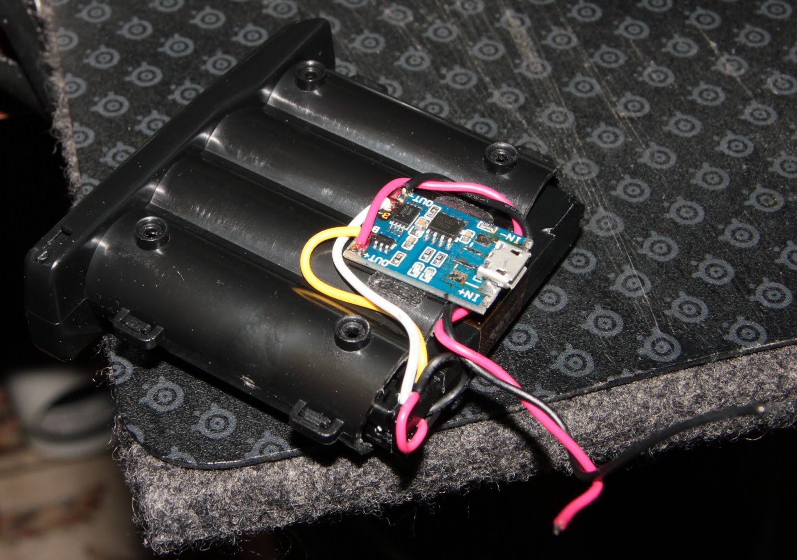

I felt a bit "fancy" today, and i figured i'd also make a little "window" to see the two little LEDs on the charging board. The even more "fancy" part was the idea of making a "lightguide" with the aforementioned RTV - it's sorta translucent, like some reeeeeally watered-down milk, or Ouzo with ice (see Ouzo effect over on Wikipedia). Should be close-to-transparent enough to see some of the LED light. But as long as i was with RTV in hand, i also squirted out a "bumper" that would press down on the inside end of the board, for good measure. There's about 3.3mm between the inside of the case and the top of the LEDs, and the lightguide's about 4mm tall, and the other "pressure point" is about 5.5mm tall. With the semiconductors and wiring being taller than the LEDs, i'm reasonably confident that should create plenty of pressure to fasten down the charging board.

Right, all buttoned-up and screwed back together. I actually had to shave off about a mm or so from the second rubber "mount" on the inside, as it turned out to have been a smidge too tall. The micro-USB socket peers through the case wall just enough to be able to plug pretty much any cable into it, for charging. It's just shy of poking over the surface, which is just right - you wouldn't want a sharp bit of pointy / edgy metal sticking out too far, and being a nuisance / hazard, do you? And the silicone-lightguide for the charging LEDs actually works about as well as i could've hoped, so i'm happy about that (too).


I'm thinking i'll actually keep it on a quasi-permanent basis installed on the 400D / XTi, as a sort of dedicated macro camera. I think i'll only be swapping it over to my other camera if / when i happen to need a video-light of some sort. But yeah, all in all, i'd call this quite a rousing success!..
No comments:
Post a Comment