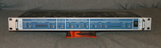
A seller on eBay had had a couple of these units listed as faulty for a few weeks, and once i had a bit of spare cash, i decided to take the dive and snap these up. The impetus was two-fold - on one hand, as it turns out, there seems to be a bit of a "disease" going around with power supplies in RME rack units; and on the other hand not long ago, i had noticed an ad from a person in this area actually looking to buy exactly one of these units.
Some extra motivation was prompted by looking up some prices for this thing. Borderline-eyewatering, i'd say. It seems to have retailed somewhere in the 1500e area at launch (1280GBP in 2003), and still selling for anything between 500-800e used (on Reverb.com or Milk Audio Store). Gulp.....
The shipping time was spent more or less being anxious whether i had bought a couple of lemons (for all i knew, the power supplies were missing altogether), or whether i would manage to catch a break and manage to fix these up easily and make some extra cash for the holidays.
Once again, i just had to go with the "don't turn it on, take it apaaaah't" approach. Big sigh of relief - both power supplies are in place.

No "skidmarks" to speak of, so "so far so good". Well, except for the spot-welding mark for the ground connection on the top case.

Nothing blown-looking or otherwise physically damaged, so hooray for that, buuuut that means it's about time for a quick power-up test. "Just in case", i put the things through the series-bulb-tester, to prevent further damage as much as possible. Flicked the switch aaaand... front panel lights in all random patterns, and a quick ticking noise coming from the power supply. Well, could be worse, but on the other hand, in line with the expectations, one might say. Second unit, similar symptoms, just a different sort of noise from the power supply.

Not exactly what one might call "uber-advanced space-age nanotech rocket science"; pretty much just your bog-standard UC3842-based (an OnSemi -B version, in this case) flyback converter, with +/-15V and +5V outputs. Although staring us right in the face is the prime suspect of this "murder" case...
Yes, the infamous "startup cap". Crime the first - Fuhjyyu TN; painfully bad news for anyone in the know. Crime the second - an electrolytic right up against the MOSFETs heatsink (which is expected to get somewhat warm-ish). Crime the third - cheaping out on THREE little capacitors? Which is that much more facepalm-worthy when all the other electrolytics both in the power supply as well as on the mainboard, are from United ChemiCon. Go figure...


Arguably cute(?) factory bodge, with the additional capacitor there...
Upon doing a quick Google search for that cap manufacturer of which we do not speak, i stumbled upon this little gem. Sure, it is of course not at all serious, but that does not preclude it from being quite appropriate.

For the more curious amongst you, the switching MOSFET is a 2SK2645. Nothing particularly special, and highly unlikely to blow up given the pretty constant load the unit should present, so there's that.
Just out of curiosity, i decided to replace that most-suspicious capacitor to see if it made any difference. Measuring the removed one showed a capacitance of merely 7uF or so, with an ESR of around 75 ohms. That's a pretty far cry from the 47uF +/-20% it's supposed to have, nevermind the colossal ESR it "achieved". Gee, i really wonder why this power supply won't start up properly... [end of sarcasm].

In addition to using a much more appropriate capacitor, i also decided to try to get as much distance from the heatsink as i could, within reason. Sure, you'd usually want to keep lead lengths to a minimum, but since we're dealing with relatively low frequencies here (<100kHz), we're not all that bothered about that. Minimizing heating is considerably more important, but that's just me. After mounting the thing back inside its "sub-enclosure" and flicking the switch, all the lights on the front panel flashed in unison 4-5 times, and then it settled into whatever modes it was set to, the last time it worked. We've got a live one!..
Just for good measure (and peace of mind), i also replaced the two other Fuhjyyu's on the secondary, flanking that upright-heatsinked axial diode. Couldn't really be bothered to trace out what they were connected to, but good riddance.
Second unit, fortunately, responded similarly well to the same treatment, so this time, i managed to luck out. Not always the case with that, though...
With that out of the way, time to handle the teardown side of things. Admittedly, RME's ADI-8 PRO tech info archive page arguably makes this somewhat redundant, what with the surprising amount of detail regarding the silicon they used, but images aren't exactly plentiful.

Running the whole show is a Xilinx XCS40XL Spartan-XL FPGA. The socketed DIP-8 chip next to it is an XCS17S40XL configuration PROM. The little SOIC-packaged one is an ST M95040 4Mbit / 512KByte SPI flash memory, while the SOT-223-packaged regulator next to it is a Texas Instruments LM1117 3.3V unit. The two clock-looking things are a pair of Epson SG531P quartz crystal oscillators - 11.2896MHz being 256 times 44.1kHz, while 24.576MHz is 512 times 48kHz. "North" of all these is a trio of Texas Instruments CD74HCT4046 PLL's. The clear labeling around each circuit block is a nice touch there.

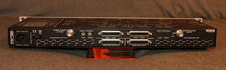
The digital input side is quite "uneventful" - BNC wordclock input, termination switch (to activate / deactivate the 75 ohm termination), two TOSLINK receivers, and a Texas Instruments 74HCT04 hex inverter.

Digital output side is even less exciting - a pair of TOSLINK transmitters, the BNC wordclock output, and another 74HCT04.

The analog side is a wee bit more populated, though. As the above-mentioned tech info page indicates, all the opamps are JRC NJM4580's (despite some cork-sniffers turning their noses up at them), followed by Analog Devices ADG451 analog switches, and feeding four AKM AK5393 analog-to-digital converters.

Arguably "more of the same" on the analog output side - a plethora of NJM4580's yet again, and a few more ADG451 switches, all fed by a quartet of Analog Devices AD1852 digital-to-analog converters.
And that just about covers it. Now, fingers crossed for the resale...
Hi,
ReplyDeleteSo happy I found your blog!
Me and many other owners of Allen&Heat Zed R16 console are trying to find a way to use Digital I/O of the mixer in the future. A&H Zed R16 has TC Applied Technologies DICE Jr Firewire chip. Do you think there is a way to upgrade it to new DICE III chip?
Thanks
Quite positive there isn't - pretty sure the physical packages, not to mention the pinouts or the firmware structure etc are quite different.
DeleteHi Khron. I have 4 Octopres MKII from Focusrite. They remained unused for a year. This week I needed the for a work a two units present a dead clock panel. No LEDs, no clock. All unlit. I checked the LEDs, all ok. Measured the voltages at the pins. All 3.4v. The back panel ADAT outs are lit. The pres are working. Phantom power working. Only the front clock panel is dead. Do you have a guess? Thanks in advance.
ReplyDeleteDo they pass audio from the analog inputs to the ADAT outputs, though?
Deletethanks so much this saved my adi 8 DS just tried swapping out the 47uf cap
ReplyDeleteVery glad to hear that, and thanks for reporting in!
Delete