First on the chopping block (as it were), a Fortin Grind.

Popping off the back cover reveals... not a whole lot. Well, maybe except for the fact that this is the black version, and (at least) the third revision.

The plastic-flap-less battery compartment is a reasonably good idea, longevity-wise. The Philips-head screws on the bottom facilitate replacing it (the battery), if/when required.
But that's not what we're all about here, is it? Out the board comes - i wanna know what make this little bastard tick. Or growl and scream, rather...

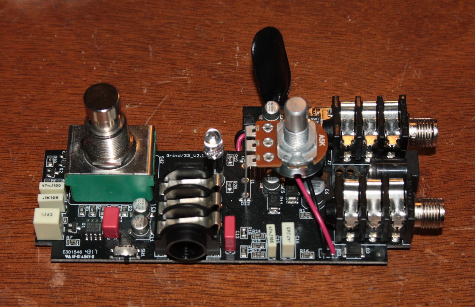
Worth starting with the nice things - Neutrik connectors, all film capacitors (ie. no ceramics in sight), and interestingly enough, a Linear Technology LT1054. Judging by all the diodes (Diodes Inc. S1BB, 100V 1A) and capacitors around it, it's likely boosting the 9V from the battery / DC input to a higher value (datasheet page 17, figure 20, plus a stage or two of a Cockroft-Walton voltage multiplier). Since 35V electrolytics seem to be used, and there's a lone TL071 on the board, i'm thinking something around 20-25V or so. 24.6V in fact, according to a quick probing.
Slightly less nice is the choice of black soldermask. For no other reason than it makes the tracing of connections and reverse-engineering more tedious and annoying. But that's never stopped ingenious people before, and it's not about to start now.
It sure took a while, but after some struggles, i managed to "decode" most of the circuit. To aid my efforts, i also recreated the rough board layout, to make a bit more sense of the traces and connections.


To be 100% honest, i'm reasonably certain there must be SOME errors in what i managed to trace out, and some chunks of the circuit don't make all that much sense to me. Also, i'm yet to manage to "decode" what those two SOT23-packaged transistors are. The "2G" marking pointed towards both PNP and NPN transistors; the PNP were "medium power", which would not make much sense here, and if memory serves, they looked like NPNs on the diode-check.
Either way, i also took the liberty of measuring the response of the thing, just to get a clearer picture. Granted, i was in a bit of a hurry when running these sweeps, and i may or may not have messed up some things regarding signal levels, but... Well, given the resulting response curve, it kinda-sorta seems like an "overly complicated" circuit. But then again, i'm no expert either, so there's that too.

Ignore the absolute dB numbers, the relative ones are much more relevant. The straight black line is with the pedal in bypass mode, while the green plot is with the pedal engaged.
With a bit of fiddling, i managed to get a kinda-sorta close curve with two filters, a 12dB/octave high-pass close to 700Hz, and a slight low-shelving boost. The slight separation between the two plots is for clarity.

Interestingly enough, the circuit is set up to provide a fixed-gain filtering function, the potentiometer being strictly an output level control. This is facilitated by the use of the LT1054 charge-pump to provide a relatively large supply voltage to the opamp, to prevent it from clipping with all but the highest-output signal sources. The highest amplification peak is just shy of 4dB (a gain of 1.6x), so with 24V supplied to the opamp, and allowing for 2V "padding" from the supply rails, that translates into a worst-case maximum input signal of around 12Vpp (around 4.4Vrms), which is well into line-level territory.
gracias!!!! por favor cuando tengas la lista de los componentes subela a un post que esperamos ansiosos!!! saludos de Latinoamerica
ReplyDeleteYou need the list of components for... what?
DeleteCan you share file project?
ReplyDeleteWhat "file project"?
Delete