
Reasonably comprehensive I/O complement, if i may say so myself, both front and back. And the inclusion of output selection, as well as transport controls, was a nice touch. Bit of a shame the tact-switches are the quite-high-actuation-force versions, stiff and clacky, which gives them a pretty cheap feel - i would've preferred a more soft-touch version, but that's just me. And since i'm not planning to keep it, i won't even bother considering replacing them.


"Obviously", the first thing to do is to rip the sucker apart, right? Now, sadly, i didn't have the presence of spirit of snapping internal photos before quickly troubleshooting it and removing the problem-component, but surely you can use your imagination to make up for my... enthusiasm, let's call it.
Top lid comes off (after removing four screws on the bottom and undoing two VERY stiff clips along the front & back edges), and after disconnecting all the cabling, 'tis all laid bare. The name is Bond - James Bond. No, wait, what?

Not exactly what i'd call a cut-rate job. Amphenol connectors (XLR combos and stacked 1/4" jacks) on the back, all name-brand chips, but that's all slightly let down by the no-name 1/4" jacks on the front edge, kinda crappy looking/feeling. But at least they bothered with heatshrink over the wire-to-pin solder joints on those, so there's that.

The brains of the operation is the Dream SAM3308B. The datasheet mentions it contains a microcontroller, as well as an audio router, and more interestingly, 8 DSP blocks. As it turns out, as i hadn't researched the unit too much beforehand, it does apparently have on-board reverb and delay effects, which is nice. The bigger chip next to it is an NXP (or nowadays, ST-NXP Wireless) ISP1582B USB peripheral controller. The S/PDIF's handled by an AKM AK4114VQ transceiver.
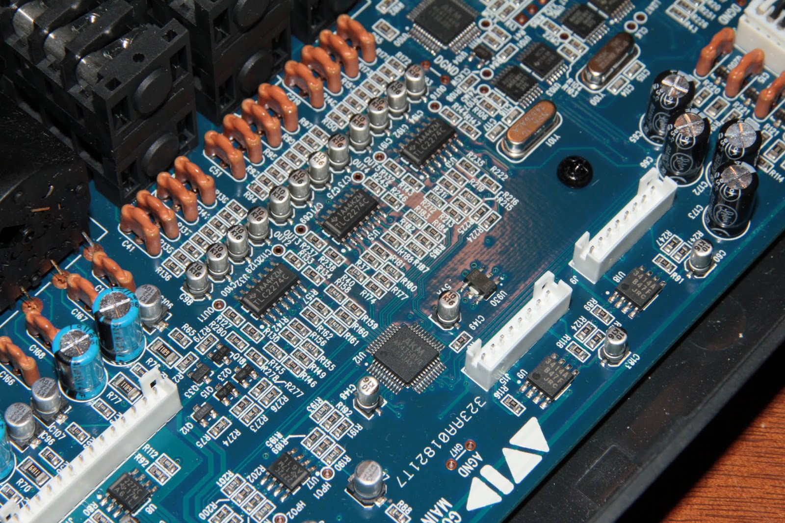
The output section is comprised of the AKM AK4358VQ 8-channel DAC, of which the first two channels go to the first pair of headphones, and the other six are the line-outs. Output low-pass filters / output buffers are three TI TLC2274C quad opamps, and two JRC NJM3414A's handle the headphone outputs themselves.

On the input side, two AKM AK5386VT handle the analog-to-digital conversion, two TI TLC2272C's buffer (and likely, or possibly, attenuate) the signals going into the ADC's, and a Fairchild/ OnSemi NDS9407 P-channel MOSFET, which my suspicion is, is soft-switching the main phantom power rail, which then is split up between the two pairs of mic inputs. Also, an AKM AK4382AT is the DAC for the second headphone output, with another TLC2272C as the output filter/buffer.

Not much to write home about, on the bottom side of the main board - the odd passive components, plus a handful of transistors likely doing some muting of the outputs on power-up/down.

Back side of the top lid is positively barren, save for the cabling connections.

The top side is a bit more "eventful", shall we say. Some shift-registers (74HC595)driving the input level meters, and others (74HC165) reading the button states. On the analog side, the mic preamps are four THAT1510's, with some TL072's after them, and one more that handles the two instrument inputs.

I liked the "nipple-lens" LED's on this board, you don't see those very often. Bit of a shame that, despite that, the slits in the top lid through which these shine, are as narrow as they are.

One more nice touch - the potentiometer knobs have a compliant rubber insert. That means that, as opposed to the more usual one-piece all-plastic ones, they won't loosen up in time, and risk sliding off. As a side-effect, due to the good grip and sealing, they were a right bastard to remove, what with the vacuum forming inside when pulling them off.
Right, time to get down to business, then. As mentioned earlier, i unfortunately only have "after" photos of the problem-area. After popping the lid off, since the thing wouldn't seem to power on at all, the obvious prime-suspect was the power supply section. Nice of the M-Audio / Avid engineers to have conveniently and clearly label some of the test-points for the various voltages. The L1 inductor was removed in order to have some "maneuvering space" - it's really cramped in there!

"P18" in the north-west of the circled area checked out just fine for the 1.8V rail. "P33" on the other hand (south-west), not so much - reading 1.5V or so. That's not gonna power on anything now, will it? After removing power, a resistance-check showed the 3.3V rail being within 13 ohms of ground.
I've revived several laptops in the past (and just the other day, the display in a 32" Vestel TV) by simply replacing a / the internally-shorted ceramic cap that was at fault. That wasn't the case here (hence the flux residue on the one nearest to the 3.3V test-point). Out comes the hot-air wand, and whaddya know - once the chip came off, no more short-circuit. Surprise, surprise...
Fortunately, it was a brand-name part as well, a Linear Technologies (nowadays, Analog Devices) LTC3407 dual synchronous buck regulator, so tracking down the cryptic "LTABA" marking was easy enough. Sanity-check, ie. measuring between the 3.3V "output" pin and the ground-connected belly-pad showed the same 13 ohms i had measured on the board.

Utterly tiny little bastard, ain't it? Micro-USB and Lightning connectors for scale ("banana for scale" wouldn't have worked, you'd likely barely even see the chip). Sure, i could've looked it up from the big distributors (Mouser etc), but since i didn't need to order anything else, shelling out 15-20$ for the shipping alone was a no-go. Fortunately there's (still) eBay, found an LTC3407A-2 from a seller who seems to be some sort of Element14 "reseller" of sorts, for about 10$ shipped. Slightly higher output capability (800mA vs. 600mA) than the original one, and higher-frequency too (2.25MHz vs. 1.5MHz) - Hopefully that won't upset things... TOO-too much.


Looking good from both sides, and upon plugging a USB cable in... Ta-daaa - 1.73V and 3.2V, well within tolerances (about 3-4% off, no biggie). I'm callin' this one fixed.
Cool!
ReplyDeleteHi, I seem to have this same problem with my C600. Where can I buy the thillte piece of shit "V2" and ... can I, who has no knowledge of micro-electronics, fix it ? Thyank you for your reply.
ReplyDeleteDan
I got mine from a British eBay seller (who seems to resell stuff from Farnell / Element14), got it delivered in a week or so.
DeleteAnd you might be able to fix it, but not without a hot-air station, i'm afraid. The chip has a metal "belly-pad" that needs to get soldered to the circuit board (for heat dissipation / heatsinking), and there's no way to do that with just a soldering iron.
Hi! I'm glad I found this blog, as I'm having a similar problem with my Fast Track C600. I'm reading 9.0ohms between P33 and DGND. P18 to DGND is fine though, >10kohm. I think my issue is the same as yours, as my U2 component gets hot when I plug the unit in.
ReplyDeleteHowever, I am able to power the unit on and switch on the 48V and inputs 3-4 and 5-6, it's just the device is never recognized by my computer (or any computer). I've tried everything I can think of on the software / driver side of things so I think my issue is that component. Would you recommend me replacing it? Looks like there's a few options on Mouser. Thanks!
9 ohms is indeed a bit low, and the 3.3V rail powers just about everything that's relevant on the digital side.
DeleteIf you want to buy it from Mouser, i'd go for the LTC3407EMSE-2PBF - the 800mA-capable version should give a bit more current-headroom than the stock 600mA one, "just in case". If memory serves, that's the one i used for reviving this unit, and i've yet to hear back from the guy i sold it to, so... Since "no news is good news", i'm left to assume it's still working fine.
By the way, I swapped the part and the short between P33 and DGND was fixed, but I'm having the same problem with it connecting to my PC. Getting 3.19V on the 3.3V line and 1.71V on the 1.8V line. Is that okay or could there be an issue elsewhere? No worries if you don't remember considering you fixed yours over two years ago lol. Appreciate the help!
DeleteHmm... Those readings aren't necessarily faulty, although they are on the ragged edge of +/-5% tolerance. Tough to say, unfortunately.
DeleteHello! Thanks for still reply to comments on this post, I have the first headphone output not working properly, I can hear the power from the amp, but the signal is so thin I have to crank the pot all the way up to hear just a smudge. I swapped the jacks and the problem is from the source, the connectors are fine. What would you say is the problem? Thank you very much in advance 🎉
ReplyDeleteSo you're getting very low volume, on headphone output 1, regardless of where you adjust the headphone volume? Does it go from "nothing" to "only very quiet"? Or is it just very quiet all the time?
DeleteIf none of the passive components near the connectors look burnt or anything, the headphone volume potentiometer could be faulty.
Thanks again! The knob works, it goes from nothing to very quiet, can you suggest me a safe range to work with the multimeter on those components around the headphone output? I should point out that output 2 works just fine, but, if you remember, the second output only works when connected to an external power supply. The problem started after I connected the interface and it started doing some very weird noises, like a funky keyboard exploding, like interference on a recording, and it kinda blew up after that, I mean, literally heard like an explosion. Thanks again 🎉🎉
DeleteSome internal photos might help.
DeleteI found a weirdly blown chip, after all it might be the cause of the problems, I also added pictures of the power phase for the jacks, which I think are ok.
Deletehttps://drive.google.com/drive/folders/1XUEtaiNlwM9LqdKdosj7fkV5_7rd05Bz?usp=sharing
after some research I found out that in fact, it can be used as a signal amplifier, so it makes sense, I ordered 10 of them through aliexpress, 5 bucks shipped to my door, so I hope it is the problem, I do think is obvious but what do I know haha, Thank you very much for the help, I will update once I swap the ics
DeleteYeah, when a chip has a crater like that in it, it should come as no surprise if it doesn't behave as it normally would or should :D And I bet it's no coincidence it's right next to those test points named "HP01" and "HP02"...
DeleteThat being said, purchasing silicon from the far east from "anonymous" sources is always a crapshoot, so... Just keep that in mind. Not saying the chips won't work, just don't be shocked if they happen not to, or end up being noisy or failing prematurely etc.
Thank you for the advice, I will test it and change it if it doesn't do it's job. I went with it because shipping from the us to me becomes very expensive, but I will do if it doesn't work well. I was so thrown away by the fact that the problem was that far back on the board, though it didn't come to my mind to read the clear hp marking haha. Thank you for answering everything, you've been very very helpful, have a good day, I'll report how it ends up working.
DeleteReliable component distributors aren't only in the US :)
DeleteAnd no problem, glad you discovered the issue, and here's to hoping there's nothing further to give you trouble!
it is the 2272C
ReplyDeleteI was able to fix it, no noise nor artifacts and the volume levels seem great, as loud as before with no distortion. Thank you so much for the help, even when it was clear what was wrong haha. Have a nice day and thanks again for everything!!
ReplyDeleteI'm very glad to hear that, and i'm happy my ("misguided"?) endeavours have helped others too :)
Deletenits just landed on my bench. Owner says no output. upon plugging it in, all lights light up except power and then nothing. Where can I find troubleshooting information for this unit?
ReplyDeleteLong story short, you can't find any. Opening the thing up and measuring the supply voltages might be a start, though.
DeleteO.k. powered the unit on, P18 to dgnd measures 1.4VDC and p33 at a measly 2VDC. Resistances once unplugged are both 10 ohms. the board gets hot around the area of the chip in question and attendant components. Could this be the same issue? If so, what to set the heat for the hot air wand to remove and replace? I do have another dead board to practice on.
ReplyDeleteWell, it wouldn't be the first of those chips in these units, that i've seen kick the bucket.
DeleteI like to surround whatever chip / component i'm about to remove, with either Kapton tape, or self-adhesive aluminium tape, just to try to keep the heat away from the things around it. Think of it as making a sort of a "bowl" or a "funnel" for the heat.
You probably won't want the smallest nozzle for the hot air, since the chip has a metal belly-pad that's soldered to the ground plane, and that'll take "some" heat to melt, so don't be shy with that.
I usually have my temperature set to 320 Celsius (whatever that may be in "Frankenstein" - thank you, AvE), and the airflow somewhere between a quarter and half. No need risking blowing components off the board...
Wow! Thank you so much! On to practicing!
ReplyDelete
ReplyDeleteHello i am getting fault but with different device, i'am have fast track ultra, problem is all channel can not active(only grey screen on channel 3456) , although wall adapter is connected.
Help me please, i can send my fast track ultra picture.
Callm me in amiroliez@gmail.com
Dear Sir
ReplyDeleteI have a problem in this typeehich is doesn't complete the booting until led no 8 bellow
Could you please tell me how I can start trouble shooting
Kind regards
Mohammad Tarrefi
Jordan
Unfortunately i don't have the faintest idea where you could start. Perhaps measuring the supply voltages, at the marked test points?
Delete