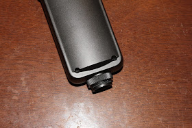
By sheer luck / accident, the other week i refreshed my Facebook main page (or "news feed" or whatever), and the first thing i saw was an ad from one of the trading groups i'm in, about a Superlux R102 (mk1) ribbon mic for sale, for a measly 30e (~$32). The seller was in a (sort-of-nearby) town i was headed to just a few days later, so i jumped at the chance. Immaculate shape, fully functional, retails for about four times as much - why not?
Comes with a blow-molded polypropylene case, and die-cut foam inserts for the mic itself, the yoke-mount and the included cable. Hey, especially for the money, i'm happy.
The only thing standing in the way of taking a peek at the insides is a pair of Phillips-head screws on the back - quite trivial, right?
The body is nice and chunky, cast aluminium (that's "aloominum" for you inhabitants of Trump-land and "Canuckistan"). I'm no expert, but if it was zinc, i kinda doubt it would've seemed as soft as it does, when attacked with an old dull box-cutter knife blade.
More or less what one might expect. We've got the magnetics up top, the step-up transformer inside the silver can in the middle, and the active gain stage on the bottom.
The ribbon itself looks a bit "floppy" to me, and not quite as corrugated nor as straight as one might expect it to be. I'll have to pose a question to people wiser than i, in this particular field. It doesn't look quite as sagged in the photo on the RecordingHacks page for this mic.
The circuitry doesn't look particularly complicated either. On a cursory visual examination, there are two 2SK117 N-channel JFETs in the input area, and two 2N5551 NPN bipolar transistors near the output. My spider-senses are slightly tingling in the direction that the latter may well be part of a Schoeps-like output stage, but i'm just speculating at this point.
As an added bonus, we've got a pair of "RuKycon" electrolytic caps - not to be confused with the Japanese Rubycon, but possibly of similar provenance as the comparably-infamous "RuLycon". Always a sign of <ahem> quality in electronics, eh?
Now, to aid in the reverse-engineering, i went with Big Clive's method of printing out the mirrored version of the bottom of the board, so all the components come up in the same places as they do when you look at the top of the board. It makes tracing out circuits oh-so-much easier.
After "filling in" the components (plus values), as well as the top-side traces, we end up with this result:
And as it turns out, i was wrong. This is not a Schoeps output circuit at all - i initially confused the NPN 2N5551's with the PNP 2N5401's (the latter polarity / orientation are employed in the Schoeps circuit). It is in fact a pair of independent buffers, basically interconnected only through the transformer at the input. Each "set" then drives the two signal lines (going to XLR pins 2 and 3, ie. "hot" and "cold" respectively), through the NPNs.
Nice touch that they used separate power supply filtering for the input JFETs and the output NPNs, that should ensure minimal interaction between the two stages.
The center-tap of the transformer is raised to mid-supply (of the input stage), as one might often see in devices like guitar pedals. Those most often use a 9V supply, and in some circuits you need to bias some points (such as op-amp inputs) at half-supply.
There is no actual gain as such, produced by the circuit (LTspice says there's actually the output is -0.6dB relative to the input), only impedance reduction. Both the JFETs and the NPNs are used as buffers, the two stages being used to their strengths (JFETs having basically nearly no input bias current but limited drive capability, while the NPNs can handle ample currents).


great post
ReplyDeleteI'm glad you found it useful.
DeleteThanks for the teardown,
ReplyDeleteI would like to see the inside of the mk2 to compare them,
im halfway there👍
Turns out my hunch was right - they wouldn't have had much reason to mess with the electronics, just tweak the ribbon motor (and perhaps the transformer?).
Deletehttp://recordinghacks.com/microphones/Superlux/R102-MKII
Nice post man, the reverse engineering schematic was really useful!
ReplyDeleteWhat are your thoughts about changing polyester caps for polyprop ones; and electolytic for low ESR polymer ones?
I guess, being the case that signal will be low and transistors are unity gain (and have considerable higher THD), caps will not matter that much. Even DC offset caused by phantom does not seem that much big of a deal (for anyone really interested see https://linearaudio.net/sites/linearaudio.net/files/Bateman%20EW%2012%202002%20mar2003%201uF%20electrolytic%20or%20film.pdf ).
I just bought one. Not many non-EQ'd mics with high freq rolloff around! Hope dont have to open mine soon tho 😅
I don't subscribe to all that (money-grabbing elitist) "voodoo" that gets peddled around, especially in the audio world. Especially with all the sub-4-figure-priced stuff present here on the blog...
DeleteFilm caps are film caps, i don't to "cork sniffing" to that extent. Where possible, sure, film caps; in a pinch, C0G / NP0 ceramics if the circuit allows or demands it (surface-mount or otherwise cramped quarters).
Low-ESR polymers have their place in high-frequency high-current (and usually low-voltage) applications. I'd expect no particular special effects at audio frequencies; if anything, they could upset (ie. trigger oscillation) linear regulators. That Bateman article is over 20 years old now, though...
On electrolytics though, my only "rule" is that i trust only the "big 5" Japanese brands (Panasonic, Nichicon, Elna, United Chemi-Con & Rubycon). And i trust recycled caps from those brands (the stash i've scavenged from various pieces of gear) way more than brand-new Chinese or even Taiwanese caps, because statistics.